2.3K
In this article we look at the all important pinouts and GPIO assignments of the webduino:bit (bpi:bit)
GPIO pin assignments
The I/O pins that are used are as follows
- RGB LED matrix: GPIO4
- Photosensitive sensor: GPIO36 (Analog A0, upper left), GPIO39 (Analog A3, upper right)
- Buttons: GPIO35 (Botton A), GPIO27 (Botton B)
- Thermistor: GPIO34 (Analog A6)
- Buzzer: GPIO25
- MPU-9250 9-axis sensor: GPIO0, GPIO21(SDA), GPIO22(SCL)
| GPIO control of webduino:bit (bpi:bit) | |||
| Light Sensor(L) | GPIO 36 | Analog Input | |
| Light Sensor(R) | GPIO 39 | Analog Input | |
| Button A | GPIO 35 | Digital Input | |
| Button B | GPIO 27 | Digital Input | |
| Thermistor | GPIO 34 | Analog Input | |
| Buzzer | GPIO 25 | PWM(Digital Output) / Analog Output | |
| RGB_LED | GPIO 4 | Digital Output | |
| MPU9250_SCL | GPIO 22 | Digital Output | |
| MPU9250_SDA | GPIO 21 | Digital Output | |
| MPU9250_INT | GPIO 16 | Digital Input | |
| R_LED(SPI_SCK) | GPIO 18 | Digital Output | |
Hardware Pin assignments
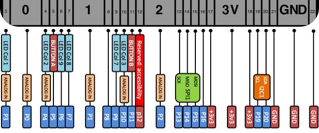
| Pin Name | Analog Function1 | Analog Function2 | Function1 | Function2 | Power |
| P3 | ADC2_CH4 | GPIO13 | |||
| P0 | ADC2_CH8 | DAC_1 | GPIO25 | ||
| P4 | ADC2_CH3 | GPIO16 | |||
| P5 | ADC1_CH7 | GPIO35 | |||
| P6 | ADC2_CH5 | GPIO12 | |||
| P7 | ADC2_CH6 | GPIO14 | |||
| P1 | ADC1_CH4 | GPIO32 | |||
| P8 | GPIO16 | ||||
| P9 | GPIO17 | ||||
| P10 | ADC2_CH9 | DAC_2 | GPIO26 | ||
| P11 | ADC2_CH7 | GPIO27 | |||
| P12 | ADC2_CH2 | GPIO02 | |||
| P2 | ADC1_CH5 | GPIO33 | |||
| P13 | GPIO18 | SPI_SS | |||
| P14 | GPIO19 | SPI_SCK | |||
| P15 | GPIO23 | SPI_MISO | |||
| P16 | GPIO05 | SPI_MOSI | |||
| 3V3 | POWER:3V3 | ||||
| 3V3 | POWER:3V3 | ||||
| 3V3 | POWER:3V3 | ||||
| P19 | GPIO22 | I2C_SCL | |||
| P20 | GPIO21 | I2C_SDA | |||
| GND | GROUND | ||||
| GND | GROUND | ||||
| GND | GROUND |