
In this article we look at an Ambient Light sensor, the LTR-329 and connect it to an ESP32
Sensor Information
The LTR-329 provides 16-bit light measurements for both Infrared and Visible+IR spectrums. Subtract one from the other to get human-visible light. Thanks to configurable gain and integration time settings, the LTR-329 can measure from 0 to 65K+ lux.
I bought an Adafruit breakout board, so the LTR-329 comes integrated with a voltage regulator and level-shifting circuitry to allow it to be used with 3.3V devices or 5V devices.
Along with a header, there is a SparkFun Qwiic compatible STEMMA QT connectors for the I2C bus so you just need to fit a suitable cable
Features
I2C interface with up to Fast Mode @ 400kbit/s with address 0x29
Ultra-small 4-pin ChipLED package 2.0mm(L), 2.0mm(B), 0.7mm(H)
Built-in temperature compensation circuit
Low active power consumption with standby mode
Supply voltage range from 2.4V to 3.6V capable of 1.7V logic voltage
Operating temperature range from -30C to +70C
RoHS and Halogen free compliant
Close to human eye spectral response
Immunity to IR / UV Light Source
Automatically rejects 50 / 60 Hz lightings flicker
Full dynamic range from 0.01 lux to 64k lux
16-bit effective resolution
Parts Required
You can connect to the sensor using dupont style jumper wire.
| Name | Link | |
| ESP32 |  |
|
| LTR329 | ||
| Connecting cables |  |
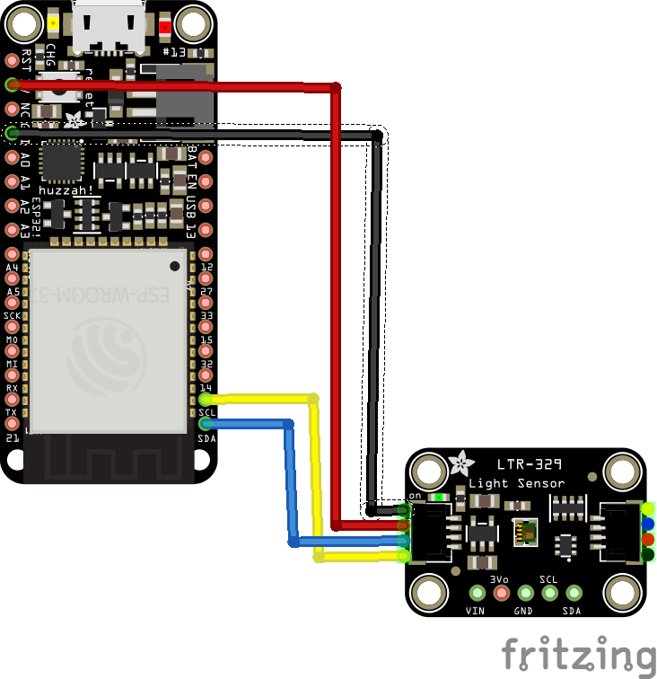
Schematic/Connection
I used 3.3v from the ESP32 and the stemma/qwic connector
Code Example
I installed the Adafruit library using the Arduino ide which also installed the dependency library
Click the Manage Libraries … menu item, search for LTR329_LTR303, and select the Adafruit LTR329 LTR303 library
If asked about dependencies, click on the “Install all” option
If the Dependencies window does appear, you already have the required dependencies installed.
If the dependencies are already installed, make sure that you have the latest ones installed using the Arduino Library Manager
This is the default ltr329_simpletest example with the delay set to 1000ms rather than 100ms which seemed a bit too short a delay for simple testing. I also removed code from the setup routine which basically displayed the settings that you can change in the setup.
These are
ltr.setGain(LTR3XX_GAIN_2);
ltr.setIntegrationTime(LTR3XX_INTEGTIME_100);
ltr.setMeasurementRate(LTR3XX_MEASRATE_200);
#include "Adafruit_LTR329_LTR303.h"

Adafruit_LTR329 ltr = Adafruit_LTR329();

void setup() {
  Serial.begin(115200);
  Serial.println("Adafruit LTR-329 advanced test");

  if ( ! ltr.begin() ) {
    Serial.println("Couldn't find LTR sensor!");
    while (1) delay(10);
  }
  Serial.println("Found LTR sensor!");

  ltr.setGain(LTR3XX_GAIN_2);
  ltr.setIntegrationTime(LTR3XX_INTEGTIME_100);
  ltr.setMeasurementRate(LTR3XX_MEASRATE_200);

}

void loop() {
  bool valid;
  uint16_t visible_plus_ir, infrared;

  if (ltr.newDataAvailable()) {
    valid = ltr.readBothChannels(visible_plus_ir, infrared);
    if (valid) {
      Serial.print("CH0 Visible + IR: ");
      Serial.print(visible_plus_ir);
      Serial.print("\t\tCH1 Infrared: ");
      Serial.println(infrared);
    }
  }

  delay(1000);
}
Output
Here is an example of what I saw in the serial monitor window – you may see some different results
This was covering and uncovering the sensor
CH0 Visible + IR: 4 CH1 Infrared: 5
CH0 Visible + IR: 4 CH1 Infrared: 5
CH0 Visible + IR: 4 CH1 Infrared: 5
CH0 Visible + IR: 3 CH1 Infrared: 4
CH0 Visible + IR: 22 CH1 Infrared: 30
CH0 Visible + IR: 20 CH1 Infrared: 29
CH0 Visible + IR: 20 CH1 Infrared: 29
Links
https://optoelectronics.liteon.com/upload/download/DS86-2014-0006/LTR-329ALS-01_DS_V1.5.PDF