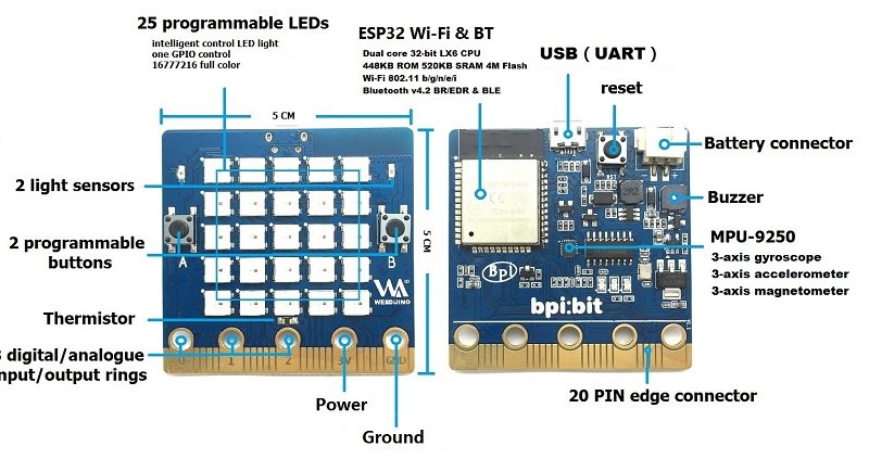
In this article we look the MPU-9250 Nine-Axis (Gyro + Accelerometer + Compass) MEMS MotionTracking™ Device which is fitted to the BPI:bit
webduino:bit
The sensor uses the following GPIO
| MPU9250_SCL | GPIO 22 | Digital Output |
| MPU9250_SDA | GPIO 21 | Digital Output |
| MPU9250_INT | GPIO 16 | Digital Input |
Parts Required
| Name | Link |
| Banana PI Bit board | Banana PI Bit board with EPS32 |
$19.50 for this board is a good price
Features
Lets look at the sensor features from the manufacturer
Gyroscope Features
The triple-axis MEMS gyroscope in the MPU-9250 includes a wide range of features:
- Digital-output X-, Y-, and Z-Axis angular rate sensors (gyroscopes) with a user-programmable full-scale range of ±250, ±500, ±1000, and ±2000°/sec and integrated 16-bit ADCs
- Digitally-programmable low-pass filter
- Gyroscope operating current: 3.2mA
- Sleep mode current: 8μA
Accelerometer Features
The triple-axis MEMS accelerometer in MPU-9250 includes a wide range of features:
- Digital-output triple-axis accelerometer with a programmable full scale range of ±2g, ±4g, ±8g and ±16g and integrated 16-bit ADCs
- Accelerometer normal operating current: 450μA
- Low power accelerometer mode current: 8.4μA at 0.98Hz, 19.8μA at 31.25Hz
- Sleep mode current: 8μA
- User-programmable interrupts
- Wake-on-motion interrupt for low power operation of applications processor
Magnetometer Features
The triple-axis MEMS magnetometer in MPU-9250 includes a wide range of features:
- 3-axis silicon monolithic Hall-effect magnetic sensor with magnetic concentrator
- Wide dynamic measurement range and high resolution with lower current consumption.
- Output data resolution of 14 bit (0.6μT/LSB) or 16 bit (15μT/LSB)
- Full scale measurement range is ±4800μT
- Magnetometer normal operating current: 280μA at 8Hz repetition rate
- Self-test function with internal magnetic source to confirm magnetic sensor operation on end products
Additional Features
The MPU-9250 includes the following additional features:
- Auxiliary master I2C bus for reading data from external sensors (e.g. pressure sensor)
- 3.5mA operating current when all 9 motion sensing axes and the DMP are enabled
- VDD supply voltage range of 2.4 – 3.6V
- VDDIO reference voltage for auxiliary I2C devices
- Smallest and thinnest QFN package for portable devices: 3x3x1mm
- Minimal cross-axis sensitivity between the accelerometer, gyroscope and magnetometer axes
- 512 byte FIFO buffer enables the applications processor to read the data in bursts
- Digital-output temperature sensor
- User-programmable digital filters for gyroscope, accelerometer, and temp sensor
- 10,000 g shock tolerant
- 400kHz Fast Mode I2C for communicating with all registers
- 1MHz SPI serial interface for communicating with all registers
- 20MHz SPI serial interface for reading sensor and interrupt registers
Code
You can roll your own code but I chose a library in the Arduino library manager called the MPU9250_asukiaaa
This is one of the default code examples
[codesyntax lang=”cpp”]
#include <MPU9250_asukiaaa.h>

#ifdef _ESP32_HAL_I2C_H_
#define SDA_PIN 21
#define SCL_PIN 22
#endif

MPU9250_asukiaaa mySensor;
float aX, aY, aZ, aSqrt, gX, gY, gZ, mDirection, mX, mY, mZ;

void setup() {
  Serial.begin(115200);
  while(!Serial);
  Serial.println("started");

#ifdef _ESP32_HAL_I2C_H_ // For ESP32
  Wire.begin(SDA_PIN, SCL_PIN);
  mySensor.setWire(&Wire);
#endif

  mySensor.beginAccel();
  mySensor.beginGyro();
  mySensor.beginMag();

  // You can set your own offset for mag values
  // mySensor.magXOffset = -50;
  // mySensor.magYOffset = -55;
  // mySensor.magZOffset = -10;
}

void loop() {
  uint8_t sensorId;
  if (mySensor.readId(&sensorId) == 0) {
    Serial.println("sensorId: " + String(sensorId));
  } else {
    Serial.println("Cannot read sensorId");
  }

  if (mySensor.accelUpdate() == 0) {
    aX = mySensor.accelX();
    aY = mySensor.accelY();
    aZ = mySensor.accelZ();
    aSqrt = mySensor.accelSqrt();
    Serial.println("accelX: " + String(aX));
    Serial.println("accelY: " + String(aY));
    Serial.println("accelZ: " + String(aZ));
    Serial.println("accelSqrt: " + String(aSqrt));
  } else {
    Serial.println("Cannod read accel values");
  }

  if (mySensor.gyroUpdate() == 0) {
    gX = mySensor.gyroX();
    gY = mySensor.gyroY();
    gZ = mySensor.gyroZ();
    Serial.println("gyroX: " + String(gX));
    Serial.println("gyroY: " + String(gY));
    Serial.println("gyroZ: " + String(gZ));
  } else {
    Serial.println("Cannot read gyro values");
  }

  if (mySensor.magUpdate() == 0) {
    mX = mySensor.magX();
    mY = mySensor.magY();
    mZ = mySensor.magZ();
    mDirection = mySensor.magHorizDirection();
    Serial.println("magX: " + String(mX));
    Serial.println("maxY: " + String(mY));
    Serial.println("magZ: " + String(mZ));
    Serial.println("horizontal direction: " + String(mDirection));
  } else {
    Serial.println("Cannot read mag values");
  }

  Serial.println("at " + String(millis()) + "ms");
  Serial.println(""); // Add an empty line
  delay(500);
}
[/codesyntax]
Output
Here is an example of my output
sensorId: 113
accelX: -0.06
accelY: -0.08
accelZ: 1.04
accelSqrt: 1.04
gyroX: 0.67
gyroY: -0.49
gyroZ: -0.55
magX: 95.13
maxY: 8.12
magZ: -105.38
horizontal direction: 85.12
at 102570ms
Links
https://www.invensense.com/products/motion-tracking/9-axis/mpu-9250/
https://www.invensense.com/download-pdf/mpu-9250-datasheet/