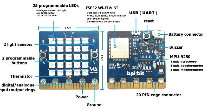
In this article we look at the 2 LDRs which are fitted to the BPI:bit
webduino:bit
If you do not know what an LDR is , here is a quick recap from wikipedia that explains them nicely
A photoresistor (or light-dependent resistor, LDR, or photo-conductive cell) is a light-controlled variable resistor. The resistance of a photoresistor decreases with increasing incident light intensity; in other words, it exhibits photoconductivity. A photoresistor can be applied in light-sensitive detector circuits, and light-activated and dark-activated switching circuits.
A photoresistor is made of a high resistance semiconductor. In the dark, a photoresistor can have a resistance as high as several megaohms , while in the light, a photoresistor can have a resistance as low as a few hundred ohms. If incident light on a photoresistor exceeds a certain frequency, photons absorbed by the semiconductor give bound electrons enough energy to jump into the conduction band. The resulting free electrons (and their hole partners) conduct electricity, thereby lowering resistance. The resistance range and sensitivity of a photoresistor can substantially differ among dissimilar devices.
The sensor uses the following GPIO pins
| Light Sensor(L) | GPIO 36 | Analog Input |
| Light Sensor(R) | GPIO 39 | Analog Input |
Parts Required
| Name | Link |
| Banana PI Bit board | Banana PI Bit board with EPS32 |
$19.50 for this board is a good price for all the features
Code
In this example we read the basic values read in from the LDRs using an analogRead, with this value then you can work out a rough light percentage. This is fairly standard LDR code that you can use.
[codesyntax lang=”cpp”]
int LDRValue0=0;
int LDRValue1=0;

void setup()
{
  Serial.begin(9600);
  //Light Sensor(L)   GPIO 36   Analog Input
  //Light Sensor(R)   GPIO 39   Analog Input
  pinMode(LIGHT_SENSOR1,INPUT);
  pinMode(LIGHT_SENSOR2,INPUT);
}

void loop()
{
  //Get the ADC values
  LDRValue0 = analogRead(LIGHT_SENSOR1);
  LDRValue1 = analogRead(LIGHT_SENSOR2);
  //Serial print
  Serial.println("-------------------------------");
  Serial.println("ADC raw value:");
  Serial.print("Left : ");
  Serial.print(LDRValue0);
  Serial.print(" Right : ");
  Serial.println(LDRValue1);
  //Get brightness Percentage
  double lumLevel0 = (LDRValue0 / 4095.00);
  double lumLevel1 = (LDRValue1 / 4095.00);
  Serial.println("Brightness level (Percentage):");
  Serial.print("Left : ");
  Serial.print((lumLevel0 * 100.00),2);
  Serial.print("%");
  Serial.print(" Right : ");
  Serial.print((lumLevel1 * 100.00),2);
  Serial.println("%");
  delay(1000);
}
[/codesyntax]
Output
Here is an example of my output, I covered the right LDR and uncovered it. you can see the values are changing in the output I saw via the Serial monitor
——————————-
ADC raw value:
Left : 4095 Right : 310
Brightness level (Percentage):
Left : 100.00% Right : 7.57%
——————————-
ADC raw value:
Left : 4095 Right : 3611
Brightness level (Percentage):
Left : 100.00% Right : 88.18%
——————————-