In this article we look at an ESP32 based board which goes by the name of ESPDUINO-32, it is also supposedly made by www.doit.am. I have seen a few clones of this board but this is what I bought

ESPDUINO-32
Here is the blurb I have seen on the internet
Overview
ESPDUINO-32 development board base on ESP-32 WiFi module, it can lead to all ESP32 module pins.
With WiFi, Bluetooth 4.2, Ethernet, real-time map and other functions, ESPduino-32 is compatible with all version of Arduino expansion boards.
Features
Control chip: Xtensa LX6 CPU
UART/EN/SPI/ENTERNET /Bluetooth 4.2
DC 5V-12V
Average current: 80 mA
1 analog input(3.2V max input) – not sure about this
Compatible with Arduino
Operating temperature:-40-85 Degrees Celsius
You need to install support for the board using the procedure in ESP32 and Arduino setup
For the board above I selected ESP32 Dev Module and the board was on COM 4, settings below
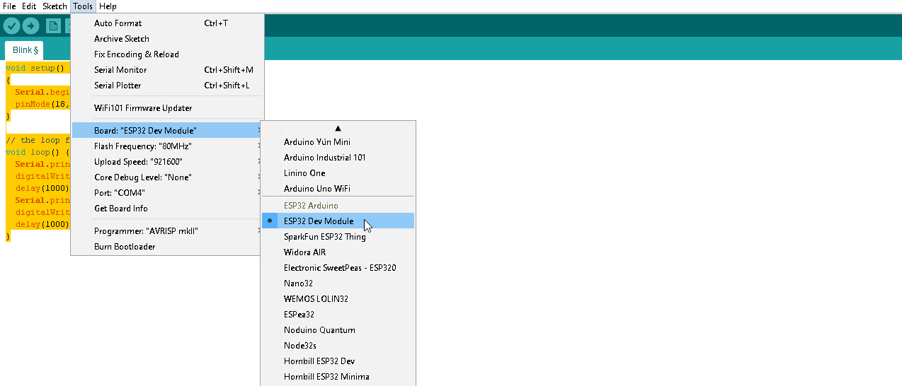
ESP32 Dev Module
Code
The standard blink sketch does not work, the BUILTIN_LED is not recognised. A clue to what you use is written down the side of the board beside the connector

esp32 connector
You’ll see pins labelled IO18, IO19 and IO23. So a quick change to the standard blink sketch – connecting an LED to IO 18 would be
[cpp]
void setup()
{
Serial.begin(115200);
pinMode(18, OUTPUT);
}
// the loop function runs over and over again forever
void loop() {
Serial.println(“HIGH”);
digitalWrite(18, HIGH); // turn the LED on
delay(1000); // wait for a second
Serial.println(“LOW”);
digitalWrite(18, LOW); // turn the LED off
delay(1000); // wait for a second
}
[/cpp]
I have seen a schematic but I do not think its this board, it looks to me like an ESP32 dev board similar to the nodemcu (ESP8266) ones that can be bought. The board is definitely usable but the claim that its compatible with arduino expansion shields is dubious. Why, well if you at the example above the LED is connected to what would be D13 on an Arduino but if you change to either D13 or 13 in the code, the example will not work.
One of the other ESP32 boards may work differently the pins_arduino.h shows how the pins are defined, for example an Arduino
#define PIN_SPI_SS (10)
#define PIN_SPI_MOSI (11)
#define PIN_SPI_MISO (12)
#define PIN_SPI_SCK (13)
The ESP32
static const uint8_t SS = 5;
static const uint8_t MOSI = 23;
static const uint8_t MISO = 19;
static const uint8_t SCK = 18;
So IO18 is the same as 13 but do’t expect 3rd party libraries to work particularly if the developer has defined pins in the library then it may well not work, if the developer has let the user define them then not an issue
Take this example from a TM1637 sketch which allows you to define the connection this can be changed
// Module connection pins (Digital Pins)
#define CLK 2
#define DIO 3
but this is in an LCD4884 library which would have to be changed based on the corresponding ESP32 pins, so just be wary of plugging in any shield and expecting it to work
// SPI Interface — (using Arduino Digital Pin 2,3,4,5,6)
#define SPI_SCK 2 //Serial Clock(Master Output)
#define SPI_MOSI 3 //Master Output,Slave Input
#define LCD_DC 4 //Data/Command(command active low)
#define SPI_CS 5 //Chip Select,Slave Transmit Enable(active low,Master Output)
#define LCD_RST 6 //One Reset button
#define LCD_BL 7//Backlit control (Arduino DIO Pin 7)
Also be wary that all of the IO pins run at 3.3V.
Its an interesting board that I will play about with considering the capabilities of the ESP32
Links