In this article we look at another interesting idea for an ESP32., its an ESP32 heart rate monitor kit.
Its an all in one development kit which contains the development board, a touch enabled LCD display and its all contained in a typical finger sensor that you get for checking your blood oxygen levels.
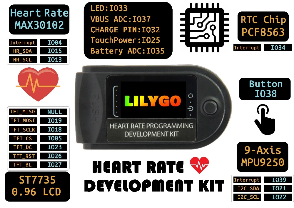
Pinout
Features
Chipset: ESP32 WIFI/Bluetooth
USB TO TTL: CP2104
LCD: 0.96 IPS LCD
Heart rate blood oxygen sensor: MAX30102
Six-axis attitude sensor chip: MPU6050
RTC: PCF8563
Customizable buttons: Button
Battery: 200mah
Charging voltage and current: 5V, 500mah
Individual sensors
MAX30102
The MAX30102 is an integrated pulse oximetry and heart-rate monitor biosensor module. It includes internal LEDs, photodetectors, optical elements, and low-noise electronics with ambient light rejection. The MAX30102 provides a complete system solution to ease the design-in process for mobile and wearable devices.
The MAX30102 operates on a single 1.8V power supply and a separate 3.3V power supply for the internal LEDs. Communication is through a standard I2C-compatible interface. The module can be shut down through software with zero standby current, allowing the power rails to remain powered at all times.
MPU-6050
The MPU-6050 devices combine a 3-axis gyroscope and a 3-axis accelerometer on the same silicon die, together with an onboard Digital Motion Processor™ (DMP™), which processes complex 6-axis MotionFusion algorithms.
The device can access external magnetometers or other sensors through an auxiliary master I²C bus, allowing the devices to gather a full set of sensor data without intervention from the system processor.
PCF8563
The PCF8563 is a CMOS1 Real-Time Clock (RTC) and calendar optimized for low power
consumption. A programmable clock output, interrupt output, and voltage-low detector are
also provided.
All addresses and data are transferred serially via a two-line bidirectional I2C-bus.
Maximum bus speed is 400 kbit/s. The register address is incremented automatically after each written or read data byte.
Development
The files are available on the github archive – https://github.com/Xinyuan-LilyGO/LilyGo-HeartRate-Kit
Download all the files from the github repository above
- Install the correct serial port driver CP210X Driver
- Change
src/main.cpptosrc.ino - Copy the files in the lib directory to
~/Arduino/libraries, Windows users copy toDocuments/Arduino/libraries - Double-click to open
src/src.ino - Change the port to the correct port and select upload
Purchase
The development board costs about £30
LILYGO®TTGO Heart Rate Programming Development Kit ESP32-D0WDQ6-V3 Flash 16MB WIFI Bluetooth IPS 0.96 LCD – Buy here