8.9K
In this article we look at a neat module which integrates a camera and an ESP32 into a 3D printed case
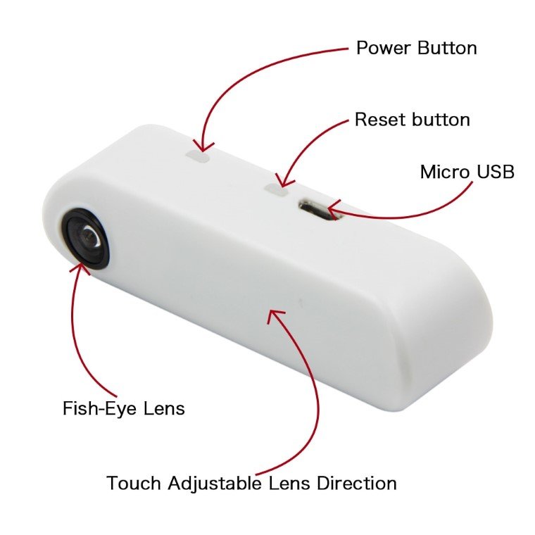
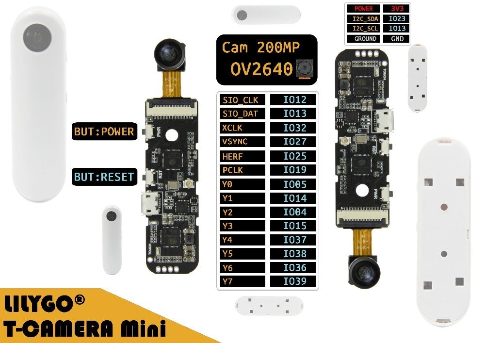
The camera is an OV2640 type and here is an image of the actual board and camera
Description
| Hardware Specifications | |
| Chipset | ESP32 Dual-Core |
| FLASH | QSPI flash 4MB / PSRAM 8MB |
| SRAM | 520 kB SRAM |
| USB to TTL | CP2104 |
| Modular interface | UART、SPI、SDIO、I2C、LED PWM、TV PWM、I2S、IRGPIO、capacitor touch sensor、ADC、DACLNA pre-amplifier |
| On-board clock | 40MHz crystal oscillator |
| Working voltage | 2.7V-3.6V |
| Working current | About 160mA |
| Working temperature range | -40℃ ~ +85℃ |
|
Power Supply Specifications |
|
| Power management Chip | AXP192 |
| Power Supply Input | USB 5V/1A |
| Charging current | 400mA |
| Battery Input | 3.7-4.2V |
| Battery | 3.7V lithium battery |
| Wi-Fi | |
| Standard | FCC/CE-RED/IC/TELEC/KCC/SRRC/NCC (ESP32 chip) |
| Protocol | 802.11 b/g/n(802.11n,speed up to150Mbps)A-MPDU and A-MSDU polymerization,support 0.4μS Protection interval |
| Frequency range | 2.4GHz~2.5GHz(2400M~2483.5M) |
| Transmit Power | 22dBm |
| Communication distance | 300m |
|
Bluetooth |
|
| Protocol | Meets bluetooth v4.2BR/EDR and BLE standard |
| Radio frequency | With -97dBm sensitivity NZIF receiver Class-1,Class-2&Class-3 emitter AFH |
| Audio frequency | CVSD&SBC audio frequency |
|
Software specification |
|
| Wi-Fi Mode | Station/SoftAP/SoftAP+Station/P2P |
| Security mechanism | WPA/WPA2/WPA2-Enterprise/WPS |
| Encryption Type | AES/RSA/ECC/SHA |
| Firmware upgrade | UART download/OTA(Through network/host to download and write firmware) |
| Software Development | Support cloud server development /SDK for user firmware development |
| Networking protocol | IPv4、IPv6、SSL、TCP/UDP/HTTP/FTP/MQTT |
| User Configuration | AT + Instruction set, cloud server, android/iOSapp |
| OS | FreeRTOS |
Quick Start
- Select ESP32 Dev Module in the Arduino board selection,and select Huge APP (3MB No OTA/1MB SPIFFS) in the Partition Scheme option,select Enable in PSRAM. Replace ssid and password in the sketch with your hotspot and password Or leave the code unchanged use AP mode
- Upload a sketch to the board
- Connect to the hotspot turned on by the board, turn on the phone to scan wifi by default, you should be able to see the hotspots sent by the board, the default is
TTGO-CAMERA-xxxx, the default is no password, open the browser and enter192.168.4.1and you will see Web interface, slide to the bottom and click Start, you will see the real-time video stream - There is a touch button under the camera, touch it, the camera screen will be reversed
- Before changing the code, you must know that this board uses integrated power management. Before coding, you must turn off the current limit of the AXP192, otherwise it may cause excessive current to cause protection.
- There are two versions of Camera Min. The earlier version is green PCB and the new version is black PCB. If using older version please turn on OLD_VERSION_CAMERA macro,in sketch 16 line
Purchase
The module costs £18 from aliexpress
LILYGO® TTGO T-Camera Mini Camera Module
Links
https://github.com/Xinyuan-LilyGO/TTGO_Camera_Mini