In this example we connect a LTR390 UV Light Sensor to an ESP32
First lets look at some information about the sensor from the manufacturer
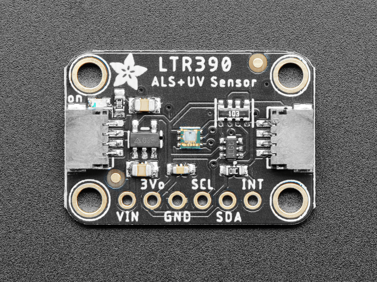
This sensor converts light intensity to a digital output signal capable of direct I2C interface.
It provides a linear ALS response over a wide dynamic range, and is well suited to applications under high ambient brightness.
The sensor has a programmable interrupt with hysteresis to response to events and that removes the need to poll the sensor for a reading which improves system efficiency.
This CMOS design and factory-set one time trimming capability ensure minimal sensor-to-sensor variations forease of manufacturability to the end customers.
Features
I2C interface capable of Standard mode @100kHz or Fast mode @400kHz communication; 1.8V logic compatible
Ambient Light / Ultraviolet light(UVS)Technology in one ultra-small 2x2mm Chip LED package
Very low power consumption with sleep mode capability
Operating voltage ranges: 1.7V to 3.6V
Operating temperature ranges: -40 to +85 ºC
Built-in temperature compensation circuit
Programmable interrupt function for ALS , UVS with upper and lower thresholds
RoHS and Halogen free compliant
UVS/ALS Features
- 13 to 20 bits effective resolution
- Wide dynamic range of 1:18,000,000 with linear response
- Close to human eye spectral response
- Automatic rejection for 50Hz/60Hz lighting flicker
This is the sensor that I bought
Parts Required
Here are the parts I used
The sensor you can pick up in the $6 price range – you can connect to the sensor using a standard header the classic dupont style jumper wire.
| Name | Link | |
| ESP32 | 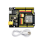 |
|
| LTR390 | ||
| Connecting cables | 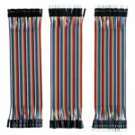 |
Schematic/Connection
The layout below shows an Adafruit Huzzah ESP32, I tried a couple of other ESP32 boards like the Lolin32 as well and they worked just fine
If you have an ESP32 board with a STEMMA QT cables, you can use these:
Black for GND
Red for V+
Blue for SDA
Yellow for SCL
I actually just extended and use this but in the layout I have shown that you can solder a header and just this as well – so you have a choice
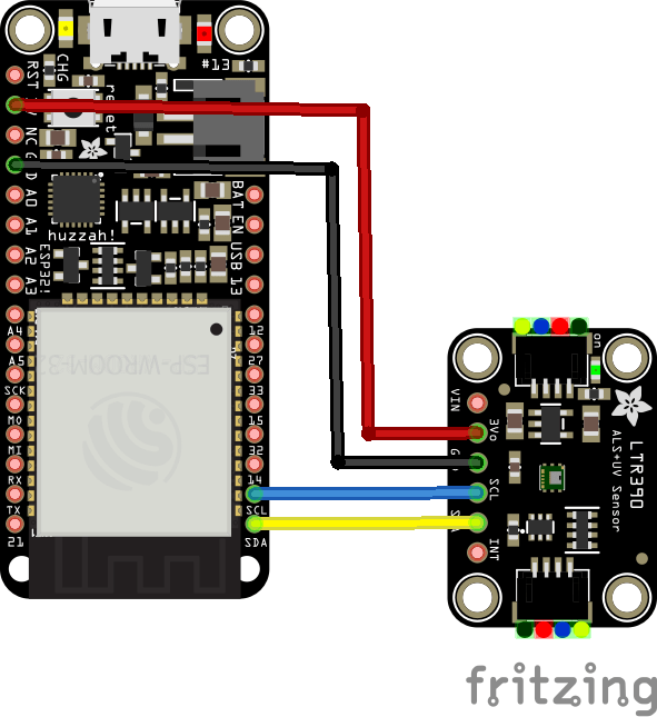
ESP32 and LTR390
Code Example
This sensor uses a couple of libraries, both of which can be installed using the library manager. if you search for the LTR390 one first and you are using a newer version of the Arduino IDE it will install the other one as well – which makes things a bit easier.
You need the Adafruit library for the https://github.com/adafruit/Adafruit_LTR390
You also need an I2C support library from the same folks for the library above to work and that is available from – https://github.com/adafruit/Adafruit_BusIO
This is the simple test example
[codesyntax lang=”cpp”]
/***************************************************
  This is an example for the LTR390 UV Sensor

  Designed specifically to work with the LTR390 UV sensor from Adafruit
  ----> https://www.adafruit.com

  These sensors use I2C to communicate, 2 pins are required to
  interface
 ****************************************************/

#include "Adafruit_LTR390.h"

Adafruit_LTR390 ltr = Adafruit_LTR390();

void setup() {
  Serial.begin(115200);
  Serial.println("Adafruit LTR-390 test");

  if ( ! ltr.begin() ) {
    Serial.println("Couldn't find LTR sensor!");
    while (1) delay(10);
  }
  Serial.println("Found LTR sensor!");

  ltr.setMode(LTR390_MODE_UVS);
  if (ltr.getMode() == LTR390_MODE_ALS) {
    Serial.println("In ALS mode");
  } else {
    Serial.println("In UVS mode");
  }

  ltr.setGain(LTR390_GAIN_3);
  Serial.print("Gain : ");
  switch (ltr.getGain()) {
    case LTR390_GAIN_1: Serial.println(1); break;
    case LTR390_GAIN_3: Serial.println(3); break;
    case LTR390_GAIN_6: Serial.println(6); break;
    case LTR390_GAIN_9: Serial.println(9); break;
    case LTR390_GAIN_18: Serial.println(18); break;
  }

  ltr.setResolution(LTR390_RESOLUTION_16BIT);
  Serial.print("Resolution : ");
  switch (ltr.getResolution()) {
    case LTR390_RESOLUTION_13BIT: Serial.println(13); break;
    case LTR390_RESOLUTION_16BIT: Serial.println(16); break;
    case LTR390_RESOLUTION_17BIT: Serial.println(17); break;
    case LTR390_RESOLUTION_18BIT: Serial.println(18); break;
    case LTR390_RESOLUTION_19BIT: Serial.println(19); break;
    case LTR390_RESOLUTION_20BIT: Serial.println(20); break;
  }

  ltr.setThresholds(100, 1000);
  ltr.configInterrupt(true, LTR390_MODE_UVS);
}

void loop() {
  if (ltr.newDataAvailable()) {
      Serial.print("UV data: ");
      Serial.print(ltr.readUVS());
  }

  delay(100);
}
[/codesyntax]
Output
Here is what I saw in Serial monitor – I was indoors at the time
UV data: 0
UV data: 0
UV data: 0
UV data: 0
UV data: 0
UV data: 0