
In this article we look at another acceleration sensor – this time its the BMA400 and we will connect it to a Wemos Lolin32
Lets look at the BMA400 – this is from the vendor
The BMA400 is the first real ultra-low power acceleration sensor without compromising on performance. Featuring 12-bit digital resolution, continuous measurement and a defined selectable bandwidth combined with ultra-low power the BMA400 allows low-noise measurement of accelerations in three perpendicular axes. The BMA400 thus senses tilt, orientation, tab/double tab, and enables plug ’n’ play step counting with activity recognition especially suited for wearable devices, which need a long-lasting battery lifetime.
Thanks to the continuous measurement principle and always-defined bandwidth, the BMA400 is the ideal solution for smart home applications such as smart indoor climate systems and smart home security systems. In the latter, the BMA400 can distinguish between real alarm situations like broken glass and false signals coming from random vibrations. Thereby, the new acceleration sensor avoids false alarms.
Features
| Parameter | Technical data |
|---|---|
| Measurement range | ±2 g, ±4 g, ±8 g, ±16 g |
| Digital resolution | 12 bit |
| Output Data Rate (ODR) | 12.5 Hz to 800 Hz |
| Low path filter bandwidth | Selectable 0.48xODR or 0.24xODR |
| Current consumption (independent from ODR due to continuous measurement) | Max. performance: 14.5 μA Typical use case: 5.8 μA Low power use case: 3.5μA |
| Noise density | Max. performance: 180 μg/√Hz (Z: x 1.45) Typical use case: 300 μg/√Hz (Z: x 1.45) Low power: 415 μg/√Hz (Z: x 1.45) |
| Ultra low power / Auto-wake-up mode | 800 nA @ 25 Hz ODR |
| Embedded features |
|
| Offset | ±80 mg |
| TCO | ±1 mg/K |
| Interface | SPI & I²C & 2 Interrupt pins |
| Supply voltage | 1.71 V up to 3.6 V |
Parts Required
| Name | Link | |
| ESP32 | 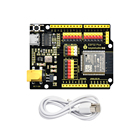 |
|
| BMA400 | ||
| Connecting cables | 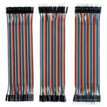 |
Schematic/Connection
| ESP32 | Module |
| 3.3v | Vcc |
| Gnd | Gnd |
| SDA/21 | SDA |
| SCL/22 | SCL |
Code Example
This uses the library from https://github.com/Seeed-Studio/Grove_3Axis_Digital_Accelerometer_BMA400
#include "BMA400.h"

float x = 0, y = 0, z = 0;
int16_t temp = 0;

void setup(void)
{
Wire.begin();

Serial.begin(115200);
while(!Serial);
Serial.println("BMA400 Raw Data");

while(1)
{
if(bma400.isConnection())
{
bma400.initialize();
Serial.println("BMA400 is connected");
break;
}
else Serial.println("BMA400 is not connected");

delay(2000);
}
}

void loop(void)
{
bma400.getAcceleration(&x, &y, &z);
temp = bma400.getTemperature();

Serial.print(x);
Serial.print(",");
Serial.print(y);
Serial.print(",");
Serial.print(z);
Serial.print(",");

Serial.print(temp);

Serial.println();

delay(500);
}
Output
Open the serial monitor and you should see something like this – I was seeing intermittent readings, BMA400 not connnected. I checked the wiring and sometimes it would work and sometimes it would not. Haven’t gotten to the bottom it
BMA400 is connected
-625.00,-804.69,189.45,32
0.00,0.00,0.00,23
-619.14,-683.59,54.69,32
0.00,0.00,0.00,23
-740.23,-712.89,-80.08,23
-656.25,-751.95,31.25,31
0.00,0.00,0.00,23
-714.84,-583.98,166.02,31
0.00,0.00,0.00,23
-849.61,-716.80,-128.91,32
0.00,0.00,0.00,23
-884.77,-433.59,62.50,32
Links
https://ae-bst.resource.bosch.com/media/_tech/media/datasheets/BST-BMA400-DS000.pdf
https://github.com/BoschSensortec/BMA400-API
https://www.bosch-sensortec.com/bst/products/all_products/bma400_1